Galvanic Isolator Gi50/16/S & Gi50/32/S
Galvanic Isolator Instructions
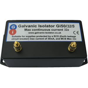
Surge Current: 120a
 The Gi50/16/S and Gi50/32/S Galvanic Isolators are intended to prevent galvanic and stray currents from finding a circulating path through the earthing connection of a shore supply. It does this by breaking the earth connection from the perspective of Galvanic/Stray currents, while ensuring an uninterrupted path to earth for fault currents. Thus the integrity of the safety electrical earth is maintained.
The Gi50/16/S & Gi50/32/S galvanic isolators are suitable for installations connected to shore supplies protected by an RCD not exceeding 30mA
Please read through these instructions. If you are not confident that you can fit this item yourself, please consult a qualified electrician or exchange the unit for our plug in isolator of similar rating, which is “plug & play”, requiring no installation.

Click Photograph to Zoom
Siting the unit:
The unit is designed for internal use, and must be placed where it will not be subject to excessive heat or physical damage. In most cases it will be located near to the point where the mains electricity supply enters the vessel.
To comply with CE standards, the earth connection of your boat must be bonded electrically to the hull.
This is a requirement of the Recreational Craft Directive, and essential for the electrical safety of the boat.
This bonding must not be broken. A simple way to ensure that any existing bonding is maintained is as follows.
-
-
- Disconnect the boat from the shore supply, and ensure that any invertors/generators etc are switched off.
-
-
-
- Disassemble the power input connection attached to the boat, and locate the EARTH terminal. This will normally have a green or green/yellow cable connected to it. It is the LONGEST pin in the connector.
-
-
-
- Disconnect the earth cable, and route it inside the boat to the place where the isolator will be located, extending it if necessary. (If there are several wires in the earth terminal, they must ALL be routed to the same place and connected to the same terminal of the isolator. This is CRUCIAL to ensure that the earth bonding is retained, and that your isolator works as intended). Label the cable(s) so that they can be identified later.
-
-
-
- Connect a new cable from the earth terminal of the power input connection, and route it inside the boat to the place where the isolator will be located. This cable should have a cross sectional area of at least 2.5mm2. Label the cable so it can be identified later.
-
-
-
- Having fixed the isolator, connect the single cable to one of the terminals on the isolator (either terminal can be used).
-
-
-
- Connect the remaining cable(s) to the other terminal of the isolator.
-
-
-
- Ensure that the connections to the isolator are secure, taking care not to overtighten.
-
-
-
- Reassemble the power input connection, ensuring that all connections are tight.
-
-
-
- The power may now be reconnected.
-
-
- Check the operation of the RCD “Test” switch.
Your galvanic isolator requires no routine maintenance, other than periodically checking that the connections remain tight. It has been designed to give many years of service, and is covered by a 5 year guarantee against faulty workmanship or parts. In the event of a major electrical fault, lightning strike etc, we recommend that your isolator is checked to confirm correct operation. We offer a free checking facility (charge for return postage applies). If you wish to take advantage of the service, please email or phone us for a returns number.
![]()