Galvanic Isolator Gi50/16/SA (Purchased Before 16/12/2016)
Galvanic Isolator Instructions Download
 The galvanic isolator protects the hull of your boat from corrosion caused by galvanic and leakage currents that arise due to chemical inter- actions between your boat and nearby boats/structures and bank- side.
The Galvanic Isolator simply connects to EITHER end of your shore line. It can be connected either at the boat end or the shore end. Both options work equally well.
 Locate your isolator where it will not be subjected to excessive heat, physical damage or water ingress, particularly the plug & socket. (Rain is acceptable – immersed or in running water is not).
When installed, to avoid water ingress, we strongly advise that the cable entries to the plug & socket should point downwards.
- Switch off the electricity supply at the shore supply
- Unplug the shore line from whichever end you choose
- Connect the isolator to the now free end of the shore line
- Connect the free end of the isolator to the boat/shore supply
- Switch on the electricity supply at the shore supply
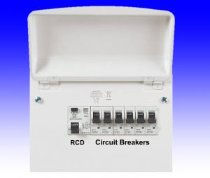
- Check that the RCD test button on the boat operates normally

Click Image to Zoom
The LED’s on your isolator inform you about any faults with your boats Earthing arrangement.
Illuminated LED’s NEVER indicate a faulty isolator. IDEALLY, the lights will be as in the picture.
Occasionally, when you fit a Status Monitored galvanic isolator, both of the warning lights may glow straight away.
If both lights are illuminated on your galvanic isolator, you have AC earth
leakage. You do NOT have a faulty isolator. In fact, your isolator is alerting
you to a potentially dangerous situation that you may not previously have
been aware of.
There are two main types of earth leakage: Mains Leakage and Imprinted Leakage.
Mains Leakage happens when an appliance, cable or connection has poor insulation resistance, and some of the circuit’s current “leaks” away to earth. If there is sufficient leakage, the earth leakage circuit breaker, also known as the RCD, will trip, disconnecting the supply.
At lower levels of leakage, the RCD may not trip, but the lights on your galvanic isolator may still glow, alerting you to the likelihood of earth leakage. Usually, an earth leakage fault will only get worse, so you should always take this seriously and investigate.
No two electrical systems are the same, so it’s only possible to give the broadest suggestions of how to locate any problem. Usually some detective work is required, and this starts by switching off the main RCD on the boat. In most cases, this will result in the lights going out. If not, there is probably something connected to the mains supply BEFORE the RCD.
Assuming the lights go out when the RCD is switched off, switch off ALL the circuit bbreakers, then switch the RCD back on. In most cases, the isolator’s lights will stay off. You can then switch the circuit breakers back on one at a time until the isolators lights come back on. The last circuit breaker you switched on has the faulty circuit, or appliance connected to it.
 Very rarely, even though all the circuit breakers (except the RCD) are switched off, the isolator lights will remain on. In this case you will need to disconnect all appliances, either by pulling out the plugs, or disconnecting any wired in appliances. Do this one at a time, taking care to ensure that you don’t forget anything. As you disconnect items, check the isolator lights. The last item you disconnect is the one causing problems.
When you have traced the fault to a single appliance or circuit, it must then be checked for earth leakage by a competent person.
Imprinted Earth Leakage
Imprinted Leakage typically occurs when equipment using a Switched Mode Power Supply Unit, (SMPSU), is connected to your system.
Equipment utilising SMPSU’s include, Battery Chargers, Computers, TV’s, Domestic Appliances, Phone Chargers etc.
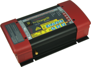 In our experience, battery chargers are often the cause of imprinted leakage. CE regulations require that equipment should not create this kind of interference, but not all equipment is as “clean” as it should be.
Because of the way SMPSU’s operate, some of them leak power into the boat’s earth wiring. This can cause the galvanic isolators light to come on, as the isolator correctly detects the leakage.
Imprinted Leakage is traced in exactly the same way as for Mains Leakage. However, when you track the problem down to an individual appliance, it may still pass an Earth Leakage test. In that case, it’s likely that the problem is Imprinted Leakage. Imprinted Leakage is often due to incorrect installation, but can also result from design or manufacturing issues.

Click Picture to Zoom
Usually, Imprinted Leakage won’t significantly degrade the performance of your isolator, and provided it is confirmed that no Mains Leakage is present, the appliance may continue to be used.
You should now read the fault indicator lights as in the picture.
Galvanic Isolator Fault Diagnosis Flowchart

Click Image to Zoom